Wednesday, August 14, 2013

Migration scenario: Migration of business process workflow data

Migration scenario: Migration of business process workflow data
For the migration scenario, you will use a simple Service Request (SR) workflow process that automatically sets the internal priority of a new SR and places it in the inbox of a service desk manager. The manager reviews the SR and places it into the queue of a service desk agent. The agent receives an automatic email notification with directions to take action based on the queued SR.
Creating the workflow process and related configuration data
Step 1:- Login to the Maximo as an administrative user.
Step 2:- Access the Roles application by navigating to System Configuration àPlatform Configuration à Roles.
Step 3:- Click the New Role button to create a new role.
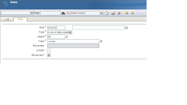
Step 4:- In the Role tab, specify the role name as ‘SDAGNT’, Type as ‘A set of data related to the record’, Object as ‘SR’ and Value as ‘:owner’ (you can use the lookup available for the Value field to select the OWNER attribute of SR). Accept other defaulted values. Save the record.
Step 5:- Access the Actions application by navigating to System ConfigurationàPlatform ConfigurationàActions.
Step 6:- Click the New Action button to create a new action.
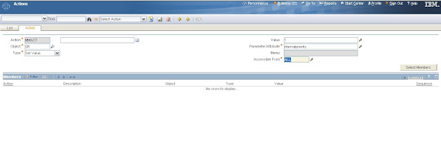
Step 7:- In the Action tab, specify the action name as ‘MMACT’, Object as ‘SR’, Type as ‘Set Value’, Value as ‘1’ and Parameter/Attribute as ‘internalpriority’ (you can use the lookup available for the Parameter/Attribute field to select the INTERNALPRIORITY attribute of SR). Accept other defaulted values. Save the record.
Step 8:- Access the Communication Templates application by navigating to System ConfigurationàPlatform ConfigurationàCommunication Templates.
Step 9:- Click the New Communication Template button to create a new communication template.
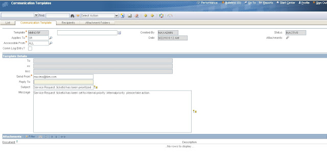
Step 10:- In the Communication Template tab, specify the Template as ‘MMNOTIF’,
Applies To as ‘SR’, Send From as an email address, Subject as ‘Service Request
:ticketid has been prioritized’, Message as ‘Service Request :ticketid has been set to internal priority :internalpriority – please take action.’ Save the record.
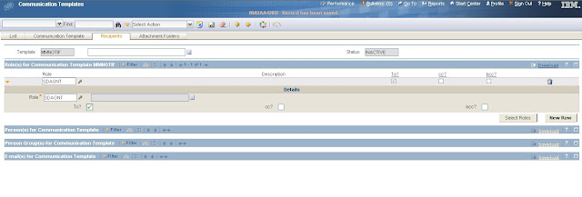
Step 11:- Now click on the Recipients tab of the Communication Templates application for the same template. Open the Roles section in the Recipients tab by clicking the Show Roles icon. Click Select Roles button. In the Select Roles lookup, search for and locate the ‘SDAGNT’ role. Check the box to the left of the role record and click OK to carry the value to the Recipients tab. Select the To check box for the role record brought back to the Recipients tab.
Step 12:- Click the Change Status button on the application tool bar. In the Change Status dialog that appears, change the status to ACTIVE.
Step 13:- Access the Workflow Designer application by navigating to System
ConfigurationàPlatform ConfigurationàWorkflow Designer
Step 14:- Click the New Process button to create a new workflow process definition.
Step 15:- In the Canvas tab, specify Process as ‘MMWF’, Object as ‘SR’.
Step 16:- Click the canvas applet to activate it. The canvas already displays Start and Stop nodes.

Step 17:-Using the canvas, drag and drop a condition node. Right click the node to bring up its properties. In the Condition Node Properties dialog, specify Title as ‘ISNEW’,
Description as ‘Is New Service Request?’, Expression as ‘:status=’NEW’’. Click OK to save the changes.
Step 18:- Drag and drop another condition node. Right click the node to bring up its properties. In the Condition Node properties dialog, specify Title as ‘ISHIPRT’, Description as ‘Is High Priority Service Request?’ Expression as ‘:reportedpriority < 3’. Click OK to save the changes.
Step 19: Drag and drop a Task node. Right click the node to bring up its properties. In the Task Node properties dialog, specify Title as ‘QUESR’, Description as ‘Queue the Service Request’ and Application as ‘SR’. Click New Row in the Assignments section and specify Role ID as ‘SDMGR’ and application as ‘SR’. Accept all other defaulted values. Click OK to save the changes
Step 20: Drag and drop positive connect lines (blue lines) between all the nodes on the canvas. Also drag and drop negative connect lines (red dashed lines) between the ISNEW, ISHIPRT condition nodes and the STOP node.
Step 21: Right click the positive connect line between the QUESR task node and STOP node. In the Action properties dialog that appears, specify Action as ‘MMACT’. Click
New Row in the Notifications section and specify the Communication Template as ‘MMNOTIF’. Accept all other defaulted values. Click OK to save the changes.
Step 22: Click save Process.
Migrating the workflow process and related data
The migration tasks to be performed are:
1. Organize the content that will encompass just the types of records listed above (workflow process, communication template, action, and role)
2. Define a migration package that will include just the records containing this newly organized content, and create, distribute and deploy a physical package based on this package definition.
Step 1A: Login as an administrative user.
Step 1b: Access the Object Structures application by navigating to System ConfigurationàMigrationàObject Structures.
Step 1c. Once the Object Structures application is displayed, type ‘DMWF%’ in the
Object Structure column of the List tab and press Enter.
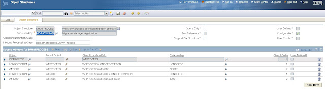
Step 1d. A single result shows up, DMWFPROCESS. This object structure organizes the content of the workflow process definition. Select this entry. The Object Structure tab opens to show you the details of the DMWFPROCESS object structure. You will notice there are 17 BOs that comprise the workflow process definition. You need not change anything here. Review the BOs and the relationships among them.
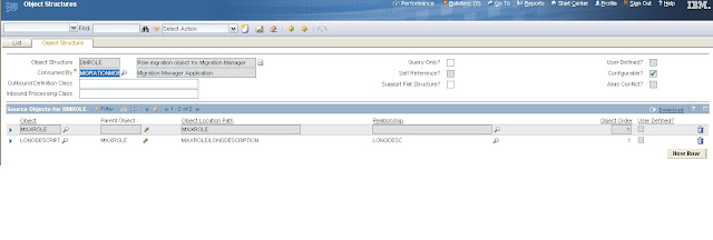
Step 1e: There is some related data to migrate as well, including the roles, notifications (communication templates), and actions. Return to the List tab of the Object Structures application. This time, enter ‘DMROLE’ in the Object Structure column. Select this entry. The Object Structure tab opens to show you the details of the DMROLE. This object structure consists primarily of MAXROLE BO.
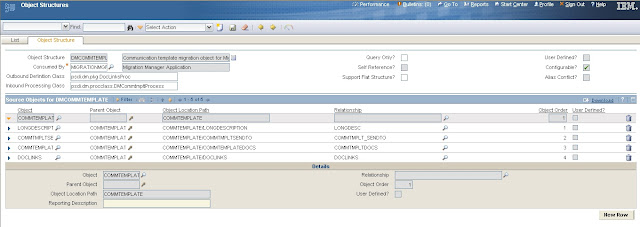
Step 1f: From the List tab of the Object Structures application, enter ‘DMCOMMTEMPLATE’. A single result shows up. Select this entry. The Object Structure tab opens to show you the details of the DMCOMMTEMPLATE object structure. Make a note of the BOs in this object structure which are primarily COMMTEMPLATE, COMMTMPLTSENDTO, and COMMTEMPLATEDOCS.


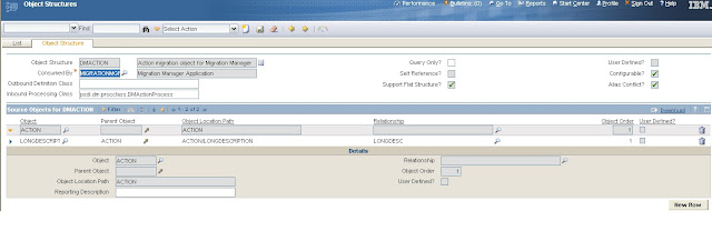
Step 1g. Finally, from the List tab of the Object Structures application, enter ‘DMACTION’ Select the DMACTION entry. The Object Structure tab opens to show you the details of DMACTION.
Step 2a: If you have logged out, login as an administrative user.
Step 2b: Access the Migration Groups application by navigating to System

Configuration à Migration à Migration Groups.
Step 2c: Once the Migration Groups application opens, hit Enter in the List tab. All the available migration groups are displayed. From this list, select the BPM (Business Process Management) entry. The Migration Group tab opens to show you the contents of the BPM group as shown below:
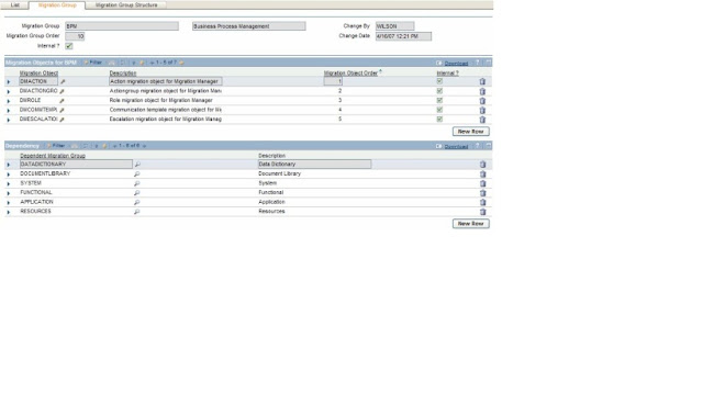


Step 2d: There are two sections: Migration Objects and Dependency. The first section,
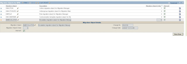
Migration Objects for BPM, lists the migration objects (object structures) that are part of the BPM group. These objects include: DMACTION, DMACTIONGROUP, DMROLE, DMCOMMTEMPLATE, DMESCALATION, DMWFPROCESS and DMINBOUNDCOMM, in that order. From this list, it is obvious that the object structures of interest are already members of the BPM group. In the current scenario, you have not built any escalation (DMESCALATION) nor do you need to migrate any Email Listener configurations (DMINBOUNDCOMM).


Step 2e: The second section, ‘Dependency’ lists other groups on which the BPM migration group is dependent. Dependencies can apply if you have put together a new custom application including new BOs, domains, tabs, and dialogs, and so on. This is not the case for the scenario. All you have to migrate is a single workflow process and its constituent data.
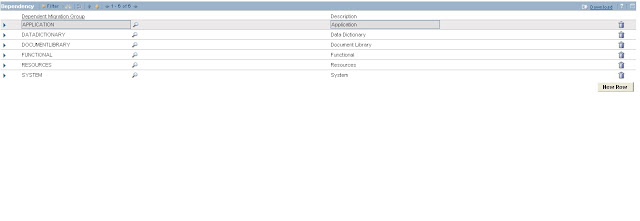
Step 2f: Since no dependencies are required, you should discard all the entries in the Dependency section. You cannot change the migration groups shipped with the product (notice they are marked ‘Internal’ in the List tab). So you will duplicate the BPM group to create MYBPM group. User-created groups can be managed as desired. In the
MYBPM group, you will discard all dependencies.
Step 2g. With the BPM group selected, drop down the Select Action menu and select
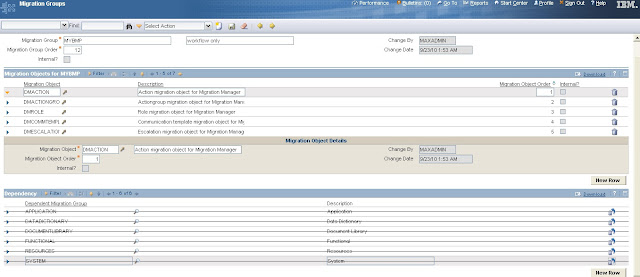
Duplicate Migration Group to duplicate the BPM group. Specify the name of the new group as ‘MYBPM’, add a description (for example, “Workflow only”). Accept the default order of 12 assigned to this new group as shown below:
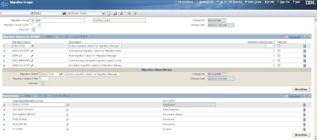
Step 2h. You can now remove the existing dependencies that were copied over from BPM. Delete each dependency using the Mark Row for Delete icon to the right in the Dependency section. This is what you should see:
Step 2i: You are now left with just the object structures that are members of the MYBPM group. You only need the DMACTION, DMROLE, DMCOMMTEMPLATE, and
DMWFPROCESS object structures. You do not need the DMACTIONGROUP, DMESCALATION, or DMINBOUNDCOMMCFG object structures because you have no changes in these areas. Delete DMACTIONGROUP, DMESCALATION, and DMINBOUNDCOMMCFG from the Migration Objects table window. Save the MYBPM group. This is what you should see:
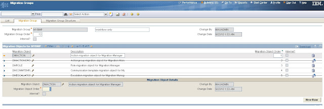
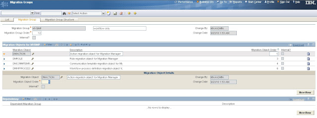
You have now created a migration group that can be used to migrate only workflow definitions and related data without other data such as Data Dictionary or Application.
This will better fit the need to carry the MMWF workflow process definition.
Step 3a: If you have logged out, login as an administrative user.
Step 3b: Access the Migration Manager application by navigating to System ConfigurationàMigrationàMigration Manager.
Step 3: Once the Migration Manager Application opens, click the New Package Definition button in the application tool bar. This causes the Package Definition tab to activate and present a new definition you can work with.
Step 3d: In the Package Definition Name field, enter a value that represents the package you want to manage. For example ‘mmwf’, Notice that the Source field has been automatically populated. Accept the default value of SNAPSHOT for the Type field.
Also accept the default value of 100 for the Batch Size field.
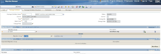
Step 3e: In this step, you will include the newly created MYBPM group in this package definition. By doing this you are declaring the content of the package to contain workflow definitions and related data. Click New Row in the Migration Groups section. In the new row that opens up, click the Detail Menu and then click Select Value. From the Select Value dialog that shows, select “MYBPM”. Once the value is returned to the Migration Groups section, click Save in the application toolbar to save this definition. This is what you should see (the Source value depends on your environment):
Step 3f: The status of the package definition is WAPPR (waiting for approval). As long as the status is pending approval, you can modify the contents of the package definition. For this particular package, leave the status at WAPPR.
Decision Point: The contents of a package definition can be modified as long as the definition status is waiting for approval.

Step 3g. Earlier, you created a single workflow process definition and some related data. The scenario calls for the migration of this one workflow process and its related data. With the current package definition, all workflow processes, all roles, all actions, and all active communication templates in the source environment will be brought into the physical package during package creation. This is not the migration requirement. You need to filter the package contents to just the specific ‘MMWF’ workflow. You can set up such a filter as part of the definition.
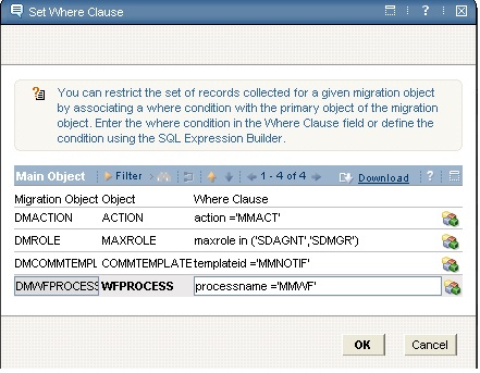
Step 3h. Click the Set Where Clause icon to the right of the MYBPM entry in the Migration Groups section. The Set Where Clause dialog opens up. This dialog now lists the migration objects included in the MYBPM group. The objects are listed in the order in which they have been included in the MYBPM group. This is what you should see:
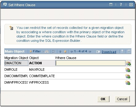
Step 3j: In this step, you will attach an SQL where condition to each migration object so that the physical package, once created, will only contain the MMWF workflow process and related records. Select the DMACTION migration object. Click the SQL Expression Builder icon to the right of this row. In the new dialog that shows up, select the ‘ACTION’ attribute. Type in the following after the attribute in the Expression field: ‘=’MMACT’’. This is what you should see:
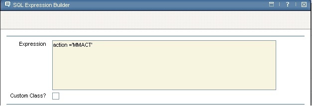
By adding this where condition, you have filtered action records to just MMACT action which is being used by workflow MMWF. Click OK to carry this where condition back into the Set Where Clause dialog for DMACTION.
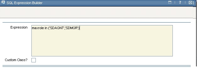
Step 3k: In the Set Where Clause dialog, select the DMROLE migration object. Click the SQL Expression Builder icon to the right of this row. In the expression builder dialog, select the MAXROLE attribute from the attribute list. Type in the following after the attribute in the Expression field: ‘in (‘SDAGNT’,’SDMGR’)’. You had two roles associated with the MMWF process. By adding this where condition, you have filtered role records to just two roles SDAGNT and SDMGR which are being used by workflow MMWF. Click OK to carry this where condition back into the Set Where Clause dialog for DMROLE.
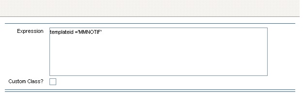
Step 3l. In the Set Where Clause dialog, select the DMCOMMTEMPLATE migration object. Click the SQL Expression Builder icon to the right of this row. In the expression builder dialog, select the TEMPLATEID attribute from the attribute list. Type in the following after the attribute in the Expression field: ‘=‘MMNOTIF’’. By adding this where condition, you have filtered communication template records to just the single template which is being used by workflow MMWF. Click OK to carry this where condition back into the Set Where Clause dialog for DMCOMMTEMPLATE.
Step 3m. In the Set Where Clause dialog, select the DMWFPROCESS migration object.
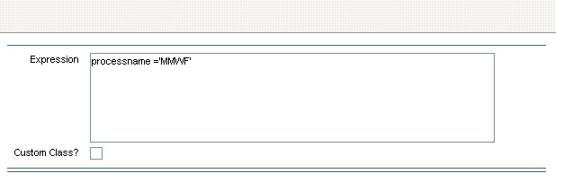
Click the SQL Expression Builder icon to the right of this row. In the expression builder dialog, select the PROCESSNAME attribute from the attribute list. Type in the following after the attribute in the Expression field: ‘=’MMWF’’. MMWF process is the only workflow process that will be included in the physical package. Click OK to carry this where condition back into the Set Where Clause dialog for DMWFPROCESS. With steps 3h through 3m, you have set up a number of filters such that only the MMWF workflow process and related artifacts are included in a physical package. Here is what you should see in the Set Where Clause dialog:
Click OK. You are now ready to approve the package.
Step 4: Click the Change Status icon in the Migration Manager Application tool bar to bring up the Change Status dialog. Drop down the list available for the Status field. Select ‘Approved Package Definition’. Click OK to approve the package definition status.
Step 5: Before you can proceed with any other package-related operations, you must activate the package. Package activation prepares it for the rest of the package life-cycle.
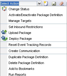
In the Migration Manager application, use the Select Action menu and drop down the list and select Activate/Deactivate Package Definition. You will notice that the Active? Check box to the right of the Package Definition tab header area is now checked. You have now completed the tasks required to prepare for a physical package.
Step 6: You can now visually verify the contents of the package definition using the Package Definition Structure tab. In the Migration Manager application, activate the Package Definition Structure tab. This brings up a hierarchical view of your package definition. To verify the contents, you can drill down into the Migration Groups node of the hierarchy. You will see MYBPM is immediately under Migration Groups. You can now expand MYBPM and verify the individual migration objects within the group. You can also open each migration object and verify each BO within the object. This visual verification step helps you determine the total contents of any physical package based on this definition.
Step 7a: For the purpose of this scenario, your target will be a folder on a file system.
The file system should be accessible to the application server where the product is executing. Later, you will download this package to your client machine.
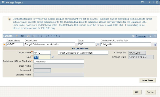
In the Migration Manager Application tool bar, click the Manage Targets icon. This brings up a dialog. Click New Row in the dialog. This creates a new row in the Targets section and opens a Target Details section below it. Enter a target name – this can be any name but must be meaningful in that it represents a target; for example, ‘3lg9r91’. Enter or select Type to be FILE since you would like to distribute the physical package in the form of a file. In the Database URL or File Path field enter ‘c: \temp’ (or other appropriate folder if you have you own local build). This is the folder into which the physical package file will be copied upon distribution. This is a folder accessible to the application server. You should see something similar to this:
Step 7b: Click OK to save this new target and dismiss the Manage Targets dialog.
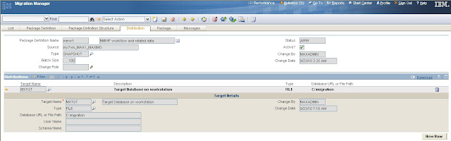
Step 7c: In this step you will link your approved package definition to the newly defined target. A distribution is what links a package to a particular target. In the Migration Manager application activate the Distribution tab. Click New Row in the Distributions section. From the new row that is created use the look up on the Target Name field or type in the target you defined in step 7a. Click Save in the application tool bar to save this distribution record. You should see something similar to this:
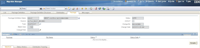
Step 8 You are now ready to create the package. In the Migration Manager application activate the Package tab. The Package tab displays an empty Packages section having a
Create button. Click the Create button. This begins the package creation. Package creation may take several minutes depending upon the volume of data to be collected.
Data collection (or export) is based entirely upon the package definition.
Step 8a: When you click the Create button, the Upload Compiled Sources dialog is displayed.
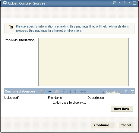
This dialog serves two purposes: 1. to collect compiled sources that should be part of the package – these files can be uploaded using this dialog. 2. To enter read me information regarding the particular physical package that can be reviewed in a target environment prior to deployment. You did not specify any compiled sources for your package, so you can ignore the Compiled Sources section. In the Read Me Information field, enter text that describes the content of the package. For example, enter “workflow artifacts for MMWF workflow targeting Service Requests”. Click Continue to continue the package creation.
No more user activity or intervention is required until the package is fully created. During package creation, the progress dialog is visible and shows messages as creation tasks progress. At the end of package creation, you should see something similar to this:
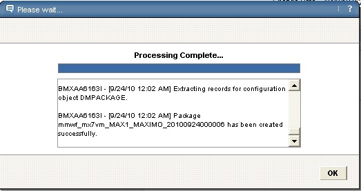
Once package creation is complete, the progress dialog shows a ‘Done’ or ‘Processing Complete’ message at the top of the dialog and enables the OK button. Click the OK button to dismiss the dialog.
Once created, the Package tab refreshes to show the new package record. The Manifest sub-tab below the Packages section shows the manifest for the package. Review the manifest and look at the listing of various migration objects that now contain actual data for the MMWF workflow process.
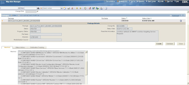
Step 9: You will distribute the newly generated package to the target you associated with the package definition. In the Migration Manager application, in the Packages section of the Package tab, select the package you created in step 8. Click the Distribute button to the right of the Create button.
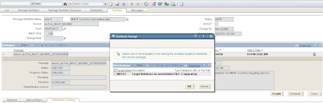
Step 9a: The Distribute Package dialog appears. This dialog lists all of the targets that have been associated with the particular package definition. In the scenario, there is only one target. Select this target by checking the box to the left of the Distribution row and click the OK button. This initiates the distribution. The progress dialog appears and messages are posted to the dialog as distribution progresses. Once complete, the dialog displays a ‘Done’ or ‘Processing Complete’ message and you click the OK button to dismiss the dialog.
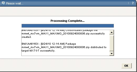
NOTE: Distribution may take several seconds or minutes depending upon how much data are to be written into the file.
You have now distributed the contents of the physical package to a file that currently resides on the application server’s file system. You can, if necessary, download this file to the client machine where you are working from.
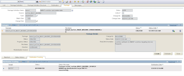
Clicking the icon will bring up the File Download dialog box with Open, Save and
Cancel buttons. This is a standard Windows® download dialog. You should see something similar to this:
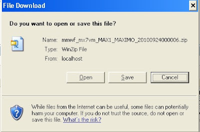
Click Save. A Save As dialog opens allowing you to choose a folder on the client machine where the file should be saved. After navigating to a folder, click Save to save the file to the particular folder on the client machine.
NOTE: You can download a package file only after you have distributed it. No file exists at the time package creation is complete.
With this step you have completed all of the migration activities necessary in the source environment. You started with the identification of changes to be migrated; you determined the need to organize content, and then defined a package that would serve as a template for physical packages. You approved and activated the definition. After associating a target with the definition, you created and distributed the package to the chosen target.

Scenario preparation in the target environment

The MMWF workflow and related records that you packaged up in source should be brought over to the target environment for testing. In this scenario, these are all new artifacts that do not exist in the test environment.
The key tasks of migration (definition, creation, distribution) have been already performed in the source environment. Just one task remains: deployment. The package that was distributed in Step 9a in the previous section of this document will now be brought into the target environment and deployed using the Migration Manager application. Step 1 In this step you will upload the package file into the target environment.
Currently, you have a copy of the file on your client machine.
Step 1a: Login to the target environment as an administrative user.
Step 1b: Navigate to the Migration Manager application using System Configurationà Migrationà Migration Manager.
Step 1c. When the Migration Manager application is displayed, the List tab of the application is active. From the Select Action menu, select the Upload Package action.
This will bring up the Upload Package dialog box as shown below:
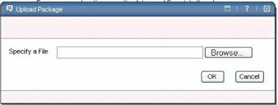
Step 1d. The Upload Package dialog box presents a Browse button. Use this button to browse your client machine and locate the package file that you had downloaded from source environment. Select the package file, click Open to bring back the folder and file information into the Upload Package dialog box. Click OK in this dialog to physically upload the package file into the test environment. The file has been placed in a sub-folder on the application server machine. The Migration Manager becomes aware that a new package is available for deployment.
Step 2: From the application toolbar, click the Deploy Package button. A popup dialog appears and this dialog displays the newly uploaded package. To the right of the package name is an icon that can be clicked to view the manifest of the package as shown below:
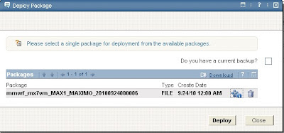
Click this icon and verify the contents of the package. The View Manifest dialog is shown below:
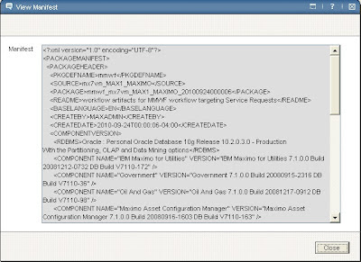
Dismiss the View Manifest dialog.
Step 3: In order to begin deployment from the Deploy Package dialog, you must first confirm that you have a database backup in place. Remember the Migration Manager has no package rollback functionality. If there is a failure in deployment, your only option to recover may be to restore your database from a backup. Check the Do you have a current database backup? Check box. Then click the Deploy button.
Step 4: Upon clicking the Deploy button, the Electronic Signature authentication dialog shows up. Enter the password for the currently logged in user and a memo into the Reason for Change field. Click OK, to proceed with deployment.
At this point a progress dialog appears and is populated with progress messages as deployment proceeds. You can watch these messages to gain a better understanding of the deployment tasks the Migration Manager performs.
Once the deployment completes, the progress dialog posts a ‘Done’ or ‘Processing
Complete’ message to the top of the dialog. The OK button is also enabled allowing you to close the dialog. The Migration Manager application is refreshed to show you the Package tab. When you review the contents of the Package tab, you will see that there is a row in the Packages tab for the package that you just deployed. It shows a status of DEPLOYED.
For this package, the deployment does not require you to log out or re-start the application server to see the changes take effect. So you can access the Workflow
Designer application and bring up the ‘MMWF’ workflow process. You will see that the workflow is laid out exactly as in the source environment. It is disabled and inactive.
Now you can validate this process, enable it, and activate it.

Join Amulyam:

http://www.amulyam.in/signup.do?id=d322ff51-6d8c-421f-8e89-12d1f2268b80

Advanced Security Configuration – Data Restrictions

Advanced Security Configuration – Data Restrictions

Data Restrictions are part of the setup of the Security Groups and can be found in the Go To menu under Security > Security Groups. Data Restrictions can be setup for any of the groups from the Data Restrictions tab and can be used to:
- - Restrict visibility of entire objects – this would be used to limit users from viewing particular Purchase Order for example those of other departments
- - Restrict visibility of particular attributes – this is used stop particular users from viewing some of the details of particular records
- - Restrict visibility of collections – restrict particular users to view only particular sets of items or companies
Before setting up Data Restrictions it necessary to setup Conditional Expressions.

Setting-Up Conditional Expressions

Conditional Expressions are setup from the Conditional Expression Manager application which can be found in the Go To menu under Administration > Conditional Expression Manager. A conditional expression is made up of the following details:
Attribute
Description
Condition Code
A reference code for the expression
Description
A brief description of the condition
Type
A value, either CLASS or EXPRESSION that defines whether the condition is attached to Java Class or SQL Expression
Expression
SQL Where Clause containing the condition under which expression is positive or negative
Class
This is a reference to the Java class which needs to be called by this Conditional Express
Always Evaluate
The always evaluate check mark should be checked for complex expressions which include references to other fields. This way the field will be re-evaluated when changes to other fields occur. Re-evaluation has a processing overhead.
Reference Count
This is a read-only field which gives the details on how many times this condition is used within particular areas of the system.
screenshot

Applying the Data Restriction

Data Restrictions are applied in Security Groups application on the Data Restriction application. The tab contains three sub-tabs:
-       Object Restrictions
-       Attribute Restrictions
-       Collection Restrictions

Object Restrictions

The object restrictions tab is used to create controls against object such as work orders, purchase order or items. It includes the following fields:
Attribute
Description
Object
The name of the object
Application
The name of the application to which the restriction should apply, if left empty it will apply to all applications
Type
This field includes the following choices:
- READONLY – the object fulfilling the condition will be shown but will be read-only
- HIDDEN – the object will not be shown in the application
- QUALIFIED – the object will not be shown in applications or look-ups
Re-Evaluate
Same as above
Condition
The condition to be used for this restriction. All objects which fulfil the condition will be restricted.
screenshot 1

Attribute Restrictions

The attribute restriction is used to hide particular attribute, such as the labor rate, or total contract value.
Attribute
Description
Object
The name of the object to be restricted
Attribute
The name of the attribute to be restricted
Application
The name of the application to which the restriction should apply, if left empty it will apply to all applications
Type
This field includes the following choices:
- READONLY – the attribute fulfilling the condition will be shown but will be read-only
- HIDDEN – the attribute will not be shown
- REQUIRED – the attribute fulfilling the condition will be shown and will be required
Re-Evaluate
Same as above
Condition
The condition to be used for this restriction. All objects which fulfil the condition will be restricted.

Collection Restriction

The collection restriction tab is used to give the group access to particular collections.

Example – Setting-Up a Conditional Expression to make Purchase Orders of a particular supplier read-only for a particular group

  1. Go to the Condition Expression Manager application
  2. Create a new Conditional Expression by clicking on the New Button and add the following details:
a.Condition Code - POREADONLY
b.Description – Vendor Read-Only
c.Type –EXPRESSION
d.Expression – :VENDOR = ‘ATI’
e.Always Evaluate – true
3.On the Security Groups application select the group to which you want to add the condition
4.On the Data Restrictions tab, select the Object Restrictions tab
5.Create a restriction by clicking the New Row button and add the following details:
a.Object –PO
b.Application – <empty>
c.Type – READONLY
d.Condition – POREADONLY
Login with a user who is part of this group and you find all the Purchase Orders related to vendor ATI as read-only.

Join Amulyam:

Tuesday, June 18, 2013

Setting up both a Cluster and Integration Framework for Maximo 7.5 on WebSphere.

Setting up both a Cluster and Integration Framework for Maximo 7.5 on WebSphere

Note:Friends this article includes the steps only no screenshots are here in this article.

Create a second application server: Name this second server MXMIF
1. Open the WebSphere Administrative Console.
2. Click Servers > Application servers, in the Application servers pane, click New.
3. In the Create New Application Server screen, enter MXMIF in the Server name field and click Next.
4. In the Select a server template screen, leave the selected “default” and click Next.
5. In the Specify server specific properties screen, check “Generate Unique Ports” checkbox, click Next.
6. Click Finish, and then click Save.
7. Heap size: Click on the new MXMIF server > Java and Process Management > Process Definition > Java Virtual Machine and fill in both the Initial and Maximum Heap sizes. Click Apply and then click Save

NOTE: When setting the maximum heap size for the MXMIF application server JVM, the admin guide says to set this to 1024MB, however, since this application server will not be used by users directly, the memory size can be increased to 2048MB so that it can handle large volumes of messages

Creating a cluster and cluster members
1.       Click Servers > Clusters, in the Server clusters screen, click New.

2.       In Step 1: Enter basic cluster information, enter MXCLUSTER in the Server name field, check Prefer local checkbox, click Next.


3.       In Step 2: Create first Clustered Servers member, enter the following:
     a. Enter MXUI1 in the Member name field.
     b. Accept the defaults in the Select Node and Weight fields.
     c. Check the Generate Unique Http Ports checkbox.
     d. Select the “Create the member using existing application server as a template” radio button and choose     MXSERVER (this is the application server name created initially for Maximo) from the drop down list and click Next.
4.       In Step 3: Create additional cluster members, enter MXUI2 in the Member name field, click Add Member and then click Next.
5.       Click Finish to create the cluster and clustered servers, then click Save

 Update Virtual Hosts
This procedure describes how to verify port numbers used by the clustered servers. It also explains how to update the virtual host with the port number information. A virtual host enables a single host machine to resemble multiple host machines. Each virtual host has a logical name and a list of one or more DNS aliases by which it is known.
1. To verify port numbers of the clustered application servers, perform the following actions:
     a. Servers > Application Servers, click MXUI1.
     b. Under the Communications, click Ports.
     c. Make a note of the WC_defaulthost port number for use below (9082, 9083).
2. Repeat Step 1 for MXUI2.
3. Environment > Virtual Hosts, click New.
4. Enter MXCLUSTER_host is the Name field, click Apply.
5. Click Host Aliases under Additional Properties.
6.      Click New in the Host Alias panel to add 3 Host name and port number values to the host aliases list:
      a. Host Name: *, Port: 80 (IBM HTTP Server port), click OK.
b. Host Name: *, Port: 9082 (same as port number for MXUI1), click OK.
c. Host Name: *, Port: 9083 (same as port number for MXUI2), click OK.
7. Click Save.

Creating data source providers for JMS stores
Set two data sources in the WebSphere console for use by the JMS resources

Note that each data source will require a unique schema, one will be used by the IF instance, and the other by the cluster. This is a WebSphere requirement that two message engines require unique schema names. As you add bus members, each member added will cause a unique message engine to be created. In this configuration there are two members, the IF instance and the cluster.

Since two schemas will be required for this configuration, and the first schema name will be the maximo schema, work with your DBA to create a second schema in the same database specifically for use by the second data source before proceeding with the steps below.

Important: The user that owns the second schema must be able to create tables.

Creating the data source provider
1.      Resources > JDBC > JDBC Providers
2. Select a valid scope from the dropdown that represents the top level (cell), such as Cell=ctgCell01.
2.      Click the "New" button.
3.      4. In Step 1: Create new JDBC provider, select the following:
a. Select your database type.
b. Select the provider type (i.e. Microsoft SQL Server JDBC Driver).
c. In the implementation type dropdown select "XA data source".
d. Click “Next”.
4.      In Step 2: Enter database class path information, enter the local path to your oraclethin.jar in the Directory location box, example: C:\ibm\SMP\maximo\applications\maximo\lib\ and click Next.
5.      Click “finish” and then click the SQL again
6.       Edit the Class path box with the correct path to the oracethin.jar as follows:
C:\ibm\SMP\maximo\applications\maximo\lib\oraclethin.jar
7.       Click Apply and then click Save.

Creating the first data source
1. Navigate back to your JDBC providers and click Microsoft SQL server JDBC Driver.
2. Click “Data sources" and then click New.
3. In Step 1: Enter basic data source information, in the Data source name field enter: oraclexads
4. In the JNDI name field, enter: jdbc/oraclexads, click “next”.
5. In Step 2: Enter database specific properties for the data source, enter the JDBC URL for your database (this can be found in your maximo.properties if you are not sure) jdbc:sqlserver://;serverName=??
6. Enter database and server name and click next.
  8. Select the Data store helper class name dropdown and select your database version, click Next. Click “Finish” and then click Save

  9. Repeat the above steps 1-8 to create a second Data source called sqlds2.


Creating your first JAAS-J2C authentication data

1. Navigate back to your JDBC provider, click Data sources, click your data source .
2. Under Related Items, click the link for "JAAS-J2C authentication data", click New.

      a.       In the alias field, enter a value you would like to use: i.e. maximo
b. Enter the username and password used to connect to the database.
c. Enter a description that identifies this entry
3. Click apply.
4. Navigate back to your data source.
5. In the dropdown field for "Component managed authentication alias", select your data alias (i.e. maximo)
6. Click Apply and then Save.
7.       Navigate to your data source again and click the test button at the top of the screen to test your data source.
 8.       Repeat steps 1-7 above to create a second JAAS-J2C authentication data named maximo2 for the oraclexads2 datasource.

Creating JMS resources for use in a clustered environment
Creating the JMS buses:
1. Service Integration/Buses, click New.
2. In Step 1: Create a new bus, enter in the name field "mifjmsbus"
3. Deselect the "Bus Security" checkbox and click “Next”, then click “Finish”.
4. Navigate to the bus you just created and select it
5. Change the "High message threshold" to 500,000 messages
6. Click "Apply" and then Save.
7. Repeat the above steps 1-7 to create a second bus called “uijmsbus”.

Adding members to the buses:
1. Service Integration/Buses
2. Select mifjmsbus, select "bus members", click Add.
3. In Step1: Select server, cluster…, select the “server” radio button, select MXMIF server from the drop down, click “next”

4. In Step 2: Select the “Data store” radio button, click Next.

5. In Step 3: Provide the message store properties,
a.       select the “Use existing data source” radio button.
b. In the data source JNDI name field, enter: jdbc/SQLDS
c. Enter the schema name for the authentication alias used by this data source (i.e. maximo).
d. Select the alias you created for this data source from the dropdown.
e. Make sure the “create tables” checkbox is checked, click Next.
6. Click “finish” and then click Save.

7. Repeat steps 1-6 above for the uijmsbus, except using maximo2 and jdbc/SQLDS2.

Setting the message store authentication alias
1. Service Integration/Buses and select mifjmsbus, select “Messaging engines”
2. Select the message engine from the list, there should be only one for the IF server

3. Under “Additional Properties” select “Message store”
4. In the authentication alias dropdown, select the maximo alias, click Apply and then click Save.

5. Repeat the above 4 steps to for the uijmsbus and maximo2 alias.


Creating bus destinations

cqin
1. Service Integration/Buses, select mifjmsbus
2. Click "Destinations", click New
3. Under Select destination type, select "Queue" and click “Next”
4. In Step 1: Set queue attributes, the Identifier field, enter "cqinbd" and click “Next”
5. In Step 2: Assign the queue to a bus member, under Bus member select Node=ctgNode01:server=MXMIF and click “Next”, then click “Finish”.
6. Navigate back to this destination, and set the exception destination radio button to “Specify” and set the value in the textbox to cqinbderr
7. Click “Apply” and click Save.
8. Repeat steps 1-7 for the cqinbderr queue.

sqin
1. Service Integration/Buses, select mifjmsbus
2. Click "Destinations", click New
3. Under Select destination type, select "Queue" and click “Next”
4. In Step 1: Set queue attributes, the Identifier field, enter "sqinbd" and click “Next”
5. In Step 2: Assign the queue to a bus member, under Bus member select Node=ctgNode01:server=MXMIF and click “Next”, then click “Finish”.
6. Navigate back to this destination, and set the exception destination radio button to “None”.
7. Click “Apply” and click Save.

sqout
1. Service Integration/Buses, select uijmsbus
2. Click "Destinations", click New
3. Under Select destination type, select "Queue" and click “Next”
4. In Step 1: Set queue attributes, the identifier field, enter "sqoutbd".
5. In Step 2: Assign the queue to a bus member, under Bus member select Node=ctgNode01:server=MXCLUSTER and click “Next”, then click “Finish”.
6. Navigate back to this destination, and set the exception destination radio button to “None”.
7. Click “Apply” and click Save.

Creating the IF connection factories
1. Resources/JMS providers
2. Select “Default Messaging Provider”, Cell=ctgCell01 scope
3. Select "Queue connection factories", click New and fill in the following:
     a. In the name field, enter "mifconfact"
     b. In the JNDI name field, enter: jms/maximo/int/cf/intcfmif
     c. Select the bus mifjmsbus from the dropdown, click "apply".
4. Go back to "Queue connection factories", click New and fill in the following:
Follow same steps as above with these values.
     a. In the name field, enter "uiconfact".
     b. In the JNDI name field, enter: jms/maximo/int/cf/intcfui
     c. Select the bus uijmsbus from the dropdown.
     d. Click "apply" and then click Save.

Create Continuous inbound error queue:
1. Resources/JMS providers
2. Select “Default Messaging Provider”, Cell=ctgCell01 scope
3. Click “Queues”, then click "New".
4. Enter the name as "CQINERR"
5. In the JNDI name field, enter "jms/maximo/int/queues/cqinerr”
6. Select the mifjmsbus as the bus for this queue from the bus name drop down
7. Select the cqinbderr queue from the queue name drop down.
8. Click "Apply".

Modify JMS queues

Continuous inbound queue:
1. Select "CQIN"
2. Select the mifjmsbus as the bus for this queue from the bus name drop down
3. Select the cqinbd queue from the queue name drop down
4. Click "Apply".


Sequential inbound queue:
1. Select "SQIN"
2. Select the mifjmsbus as the bus for this queue from the bus name drop down
3. Select the sqinbd queue from the queue name drop down
4. Click "Apply".


Sequential outbound queue:
1. Select "SQOUT"
2. Select the uijmsbus as the bus for this queue from the bus name drop down
3. In Select the sqoutbd queue from the queue name drop down
4. Click "Apply" and then click Save.

Creating the JMS Activation Specifications
1. Resources/JMS/Activation specifications.
2. If it already exists, select and delete the current Activation specification “intjmsact”

3. Resources/JMS/JMS providers
4. Select “Default Messaging Provider”, Cell=ctgCell01 scope
5. Click “Activation specifications”, then click "New".
     a. In both the Name field and the JNDI name field, enter "intjmsact"
     b. In the "Destination JNDI name" field, enter "jms/maximo/int/queues/cqin"
     c. Select the bus "mifjmsbus" from the bus name drop down
     d. Set Maximum batch size to 10, set Maximum concurrent end points to 5
6. Click Apply
7. Repeat the steps above for a second activation specification called “intjmsacterr”
     a. both the Name field and the JNDI name field, enter "intjmsacterr"
     b. In the “Destination JNDI name” field, enter “jms/maximo/int/queues/cqinerr”
     c. Select the bus "mifjmsbus" from the bus name drop down
     d. Set Maximum batch size to 1, set Maximum end points to 10
8. Click “apply” and then click Save.

Changes required in Maximo
1. Launch the Maximo application and log in:
http://host:port/maximo
2. Navigate to the Integration/External Systems application
3. Select any external system and then from the Select action menu, select add/modify queues
4. Modify the connection factory names for your queues to match the names created above and the Maximum try count value as below:

Continuous inbound queue:
Queue JNDI name: jms/maximo/int/queues/cqin
Queue Connection Factory: jms/maximo/int/cf/intcfmif
Maximum Try count: 3


Queue JNDI name: jms/maximo/int/queues/cqinerr
Queue Connection Factory: jms/maximo/int/cf/intcfmif
Maximum Try count: 0

Sequential inbound queue:
Queue JNDI name: jms/maximo/int/queues/sqin
Queue Connection Factory: jms/maximo/int/cf/intcfmif
Maximum Try count: 0


Sequential outbound queue:
Queue JNDI name: jms/maximo/int/queues/sqout
Queue Connection Factory: jms/maximo/int/cf/intcfui
Maximum Try count: 0

5. Save your changes.

6. Configure you JMS crontasks
·  On the navigation bar, click Go To > System Configuration > Platform Configuration > Cron Task Setup.
·  On the List tab in the Cron Task Setup application, select the JMS Sequential Queue Consumer cron task (JMSQSEQCONSUMER).
·  On the Cron Task tab in the Cron Task Instances table window, select the SEQIN cron task instance.
·  In the SEQIN cron task instance, select the Active check box.
·  In the Cron Task Instances table window, select the SEQOUT cron task instance.
·  In the SEQOUT cron task instance, select the Active check box.
·  After you have selected the required check boxes, click Save Cron Task Definition


Build and deploy multiple EAR files from the same Maximo directory.
You will need to build multiple ear file builds of Maximo where some of the files to be included in each ear file will be different from the next, you do not need multiple instances of the Maximo installation folder.
For example, the User Interface application server requires one ear file that disables the IF Inbound crontasks and the Integration Framework application server requires an ear file that disables the Outbound crontasks.

For each file that will be modified making it different for one ear from the next, make a copy of that file and name it appropriately. An example of the files that would be unique to each ear file for the above scenario might look like this:

maximo.properties
maximo.propertiesUI
maximo.propertiesIF


ejb-jar.xml
ejb-jarUI.xml
ejb-jarIF.xml


ibm-ejb-jar-bnd.xmi
ibm-ejb-jar-bndUI.xmi
ibm-ejb-jar-bndIF.xmi


Where there are 3 copies of each file, one with the default name, the next named for the User Interface ear, and one named for the Integration Framework ear.


In this scenario, for two ears you would make two copies of the file buildmaximoear.cmd and give them names such as the following:

buildmaximoear-UI.cmd
buildmaximoear-IF.cmd

These would be the files you use to build your individual ear files.

These are the steps to change the new cmd files to build your unique ear files:

1. Edit the buildmaximoear-UI.cmd file, and at the top, enter the following shell commands:

copy /Y \ibm\SMP\maximo\applications\maximo\properties\maximo.propertiesUI \ibm\SMP\maximo\applications\maximo\properties\maximo.properties
copy /Y \ibm\SMP\maximo\applications\maximo\mboejb\ejbmodule\meta-inf\ejb-jarUI.xml \ibm\SMP\maximo\applications\maximo\mboejb\ejbmodule\meta-inf\ejb-jar.xml
copy /Y \ibm\SMP\maximo\applications\maximo\mboejb\ejbmodule\meta-inf\ibm-ejb-jar-bndUI.xmi \ibm\SMP\maximo\applications\maximo\mboejb\ejbmodule\meta-inf\ibm-ejb-jar-bnd.xmi

2. Change the EAR_FILENAME variable to reflect the unique ear file name for the UI and IF, for example:

set EAR_FILENAME=maximoUI.ear

3. You can then run this build scripts to build the ear files. In this case, the resulting ear file will be named maximoUI.ear.


4. Repeat the above steps to create the maximoIF.ear as well, changing references from UI to IF.

Prepare the UI application


1. Edit the maximo.propertiesUI file and add the donotrun option as below:
a. mxe.crontask.donotrun=JMSQSEQCONSUMER.SEQQIN, BBCron.BBCRON1, ESCALATION. ESCESCBLTNEXP, REPORTLOCKRELEASE, REPORTLOCKRELEASE1, REPORTUSAGECLEANUP, REPORTUSAGECLEANUP1


Since we want almost all of the crontasks to run in the IF instance, all crontasks will be listed here except for the JMSQSEQCONSUMER.SEQQOUT - this crontask will need to run in the UI instance.

Note: Use of the above donotrun option is recommended over the target-enabled option because the donotrun option is Cluster-aware. Therefore, if the crontask is running in one application server, and that application server is shut down, another application server can take over running the crontasks.

Be sure to go through your list of crontasks and note each instance in the correct case and add it to the mxe.crontask.donotrun parameter in the maximo.propertiesUI, each separated by a comma

2. Build the maximoUI.ear file.


Prepare the IF application

For the MXMIF application instance, edit the following files and uncomment the message driven beans for the continuous queues:

1. Locate the file under \ibm\SMP\maximo\applications\maximo\mboejb\ejbmodule\meta-inf\ejb-jarIF.xml and edit the file and make sure the following four sections are uncommented to look like below:

<!-- MEA MDB -->
<message-driven id="MessageDriven_JMSContQueueProcessor_1">
<ejb-name>JMSContQueueProcessor-1</ejb-name>
<ejb-class>psdi.iface.jms.JMSContQueueProcessor</ejb-class>
<transaction-type>Container</transaction-type>
<message-destination-type>javax.jms.Queue</message-destination-type>
<env-entry>
<env-entry-name>MESSAGEPROCESSOR</env-entry-name>
<env-entry-type>java.lang.String </env-entry-type>
<env-entry-value>psdi.iface.jms.QueueToMaximoProcessor</env-entry-value>
</env-entry>
</message-driven>


<!-- MEA MDB for error queue -->
<message-driven id="MessageDriven_JMSContQueueProcessor_2">
<ejb-name>JMSContQueueProcessor-2</ejb-name>
<ejb-class>psdi.iface.jms.JMSContQueueProcessor</ejb-class>
<transaction-type>Container</transaction-type>
<message-destination-type>javax.jms.Queue</message-destination-type>
<env-entry>
<env-entry-name>MESSAGEPROCESSOR</env-entry-name>
<env-entry-type>java.lang.String </env-entry-type>
<env-entry-value>psdi.iface.jms.QueueToMaximoProcessor</env-entry-value>
</env-entry>
<env-entry>
<env-entry-name>MDBDELAY</env-entry-name>
<env-entry-type>java.lang.Long </env-entry-type>
<env-entry-value>30000</env-entry-value>
</env-entry>
</message-driven>


<!-- MEA MDB -->
<container-transaction>
<method>
<ejb-name>JMSContQueueProcessor-1</ejb-name>
<method-name>*</method-name>
</method>
<trans-attribute>Required</trans-attribute>
</container-transaction>

<!-- MEA MDB for error queue -->
<container-transaction>
<method>
<ejb-name>JMSContQueueProcessor-2</ejb-name>
<method-name>*</method-name>
</method>
<trans-attribute>Required</trans-attribute>
</container-transaction>


2. Locate the file under \ibm\SMP\maximo\applications\maximo\mboejb\ejbmodule\meta-inf\ibm-ejb-jar-bndIF.xmi and edit the file using a text editor and make sure the following 2 sections are uncommented to look like below:

<!-- MEA MDB -->
<ejbBindings xmi:type="ejbbnd:MessageDrivenBeanBinding" xmi:id="MessageDrivenBeanBinding_1" activationSpecJndiName="intjmsact">
<enterpriseBean xmi:type="ejb:MessageDriven" href="META-INF/ejb-jar.xml#MessageDriven_JMSContQueueProcessor_1"/>
</ejbBindings>

<!-- MEA MDB for error queue -->
<ejbBindings xmi:type="ejbbnd:MessageDrivenBeanBinding" xmi:id="MessageDrivenBeanBinding_1" activationSpecJndiName="intjmsacterr">
<enterpriseBean xmi:type="ejb:MessageDriven" href="META-INF/ejb-jar.xml#MessageDriven_JMSContQueueProcessor_2"/>
</ejbBindings>
3. Edit the maximo.properties file and add the donotrun option as below:
a. mxe.name=MXMIF
b. mxe.crontask.donotrun=JMSQSEQCONSUMER.SEQQOUT


Note: SEQQOUT will be the only crontask entry because this is the only crontask that we do not want to run.

4. Rename the current maximo.ear (for keeping) and then build the maximo.ear. When the new ear has been built, rename the new ear to ”mxmif.ear”.


Deploy both the UI and IF applications

1. Deploy both ear files:
a. The maximoUI.ear will be deployed to the MXCLUSTER, when mapping modules to servers make sure you select both the MXCLUSTER as well as the webserver1 and when mapping virtual hosts to web modules use the virtual host you created above: MXCLUSTER_host
b. The maximoIF.ear will be deployed to the MXMIF application, for the application name change from "MAXIMO" to MXMIF. When mapping modules to servers make sure you select both the MXMIF as well as the webserver1 and when mapping virtual hosts to web modules use the virtual host you created above: maximo_host


2. Start the MXCLUSTER Cluster and the MXMIF application server.

The Integration Global Directory:

When you deploy a web service, a folder called Axis2 is updated with the service you have just deployed. This file will be written under to root folder of the Integration Global Directory. If WebSphere application servers will be distributed in a multi-node environment, the integration global directory must exist in a shared location that all application servers can access.

This directory is used for error file extract and wsdl files for web services.
This shared location can be either a mapped drive or UNC share (Windows), or a mount point (Unix). The user specified to run the WebSphere services must have access to read and write to this share or mount point. This includes the node agent. In Windows, do not use a local system account to start Windows services but rather a domain account as local system accounts to not have access to mapped drives or UNC shares.

You set the integration global directory path in the System Properties application, the property is called mxe.int.globaldir.
Deploying web services

When deploying web services, you will need to set up the web service administration URL and port to point to the MXMIF application server IP address and port. When sending transactions to these interfaces, you will need to point your web service client to the IP address and port of the MXMIF application server IP address and port, not the cluster address for the UI instances

It is also important to make sure that the Integration Global Directory is in a location that all application servers in a multi-node environment can access. See the next section for information on the Integration Global Directory.